Increase the bass output of your present instrument at modest cost!
Bass Boost is todays sound... whether its the driving, gut-vibration pulsation of disco, or the solid bass line of soft, hard, or laid-back rock. One way to get the modern bass-boost sound without running out and buying an all-new expensive piece of equipment is to use a Bass Booster between your guitar, electronic organ or what-have-you, and the instrument amplifier.
A bass booster strips the highs from the instruments output signal and amplifies low frequencies, feeding on "all-bass" sound to the instrument amplifier. Naturally, the bigger the speaker used with the amp, the more powerful the bass: use 15-inchers with the Bass Booster and you can rattle the windows. Bass Booster is powered by an ordinary 9 volt transistor radio battery. It can be assembled on a small printed board or on a veroboard using point to point wiring. The booster connects between your instrument and its amplifier through two standard RCA Jacks.
Circuit Diagram:
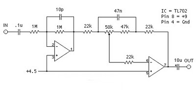
 Bass Booster Circuit Diagram
P1 = 50K
P2 = 100K
R1 = 22K
R2 = 470K
R3 = 47K
R4 = 10K
R5 = 470R
R6 = 1K
Q1 = 2N2222
C1 = 2.2uF-25v
C2 = 100nF-63v
C31 = 00nF-63V
C4 = 3.3uF-25v
C5 = 470uF-25v
D1 = 5mm. Red Led
Q1 = 2N2222
B1 = 9v Battery
J1 = RCA Audio Input Socket
J2 = RCA Audio Output Socket
S1 = On-Off Switch
Using Bass Booster:
Connect your electronic guitar or other electronic instrument to input jack J1; Connect output jack J2 to your instruments amplifiers normally-used input. With power switch S1 off, key S2 so the instrument feeds directly to the instrument amplifier. With P2 set full counter-clockwise (Off), turn power switch S1 on, key S2 once, and advance P2 for the desired Bass Boost level. To cut back to natural sound just stomp down on S2 and key the Bass Booster out. Dont worry about leaving power switch S1 on for several hours of a gig. The circuit pulls less than 1mA from the battery, so battery will last many, many months.
source :http://www.ecircuitslab.com