Showing posts with label amplifier. Show all posts

Sunday, December 22, 2013

Simple Video Amplifier

The video amplifier in the diagram is a well-known design. Simple, yet very useful, were it not for the ease with which the transistors can be damaged if the potentiometers (black level and signal amplitude) are in their extreme position. Fortunately, this can be obviated by the addition of two resistors.

Circuit diagram :

Simple Video Amplifier-Circuit Diagram Simple Video Amplifier Circuit Diagram


If in the diagram R 3 and R 4 were direct connections, as in the original design, and P 1 were fully clockwise and P 2 fully anticlockwise, such a large base current would flow through T 1 that this transistor would give up the ghost. Moreover, with the wiper of P 2 at earth level, the base current of T 2 would be dangerously high. Resistors R 3 and R 4 are sufficient protection against such mishaps, since they limit the base currents to a level of not more than 5 mA.

Shunt capacitor C 4 prevents R 4 having an adverse effect on the amplification.

ReadMore..

Tuesday, October 8, 2013

Headphone Amplifier Using Discrete Components

An amplifier to drive low to medium impedance headphones built using discrete components.

Both halves of the circuit are identical. Both inputs have a dc path to ground via the input 47k control which should be a dual log type potentiometer. The balance control is a single 47k linear potentiometer, which at center adjustment prevents even attenuation to both left and right input signals. If the balance control is moved towards the left side, the left input track has less resistance than the right track and the left channel is reduced more than the right side and vice versa. The preceding 10k resitors ensure that neither input can be "shorted" to earth.

Headphone Amplifier Circuit DiagramAmplification of the audio signal is provided by a single stage common emitter amplifier and then via a direct coupled emitter follower. Overall gain is less than 10 but the final emitter follower stage will directly drive 8 ohm headphones. Higher impedance headphones will work equally well. Note the final 2k2 resistor at each output. This removes the dc potential from the 2200u coupling capacitors and prevents any "thump" being heard when headphones are plugged in. The circuit is self biasing and designed to work with any power supply from 6 to 20 Volts DC.
ReadMore..

Monday, October 7, 2013

14W CLASS A AMPLIFIER USING 2N3055 ELECTRONIC DIAGRAM

14W CLASS A AMPLIFIER USING 2N3055 ELECTRONIC DIAGRAM

Why Class A ? Because , when biased to class A, the transistors are always turned on, always ready to respond instantaneously to an input signal. Class B and Class AB output stages require a microsecond or more to turn on. The Class A operation permits cleaner operation under the high-current slewing conditions that occur when transient audio signal are fed difficult loads. His amplifier is basically simple, as can be seen from the block diagram.
ReadMore..

Monday, September 2, 2013

Audio Amplifier with High Clarity Circuit

Circuit Diagram

Description
The heart of the circuit is TDA7294 which acts as an amplifier the right and left input feded from the pre amplifier circuit is amplified after passing through the noise filter which contains an RC circuit, the volume is controlled by the variable resistor 47k. and the automatic gain control is provided by the operational amplifier circuit opp amp IC249 For both right channel and left channel., the speaker used is an 8 ohms 40 watts speaker. 

ReadMore..

Thursday, August 8, 2013

Simple Automatic Switch For Audio Power Amplifier

Circuit of an automatic switch for audio power amplifier stage is presented here. The circuit uses stereo preamplifier output to detect the presence of audio to switch the audio power amplifier on only when audio is present. The circuit thus helps curtail power wastage. IC1 is used as an inverting adder. The input signals from left and right channels are combined to form a common signal for IC2, which is used as an open loop comparator. IC3 (NE556) is a dual timer. Its second section, i.e., IC3(b), is configured as monostable multivibrator. Output of IC3(b) is used to switch the power amplifier on or off through a Darlington pair formed by transistors T1 and T2. IC3(a) is used to trigger the monostable multivibrator whenever an input signal is sensed.

Circuit diagram:
Automatic Switch For Audio Power Amplifier-Circuit-Diagram
Automatic Switch For Audio Power Amplifier Circuit Diagram

Under ‘no signal’ condition, pin 3 of IC2 is negative with respect to its pin 2. Hence the output of IC2 is low and as a result output of IC3(a) is high. Since there is no trigger at pin 8 of IC3(b), the output of IC3(b) will be low and the amplifier will be off. When an input singal is applied to IC1, IC2 converts the inverted sum of the input signals into a rectangular waveform by comparing it with a constant voltage which can be controlled by varying potentiometer VR1. When the output of IC2 is high, output pin 5 of IC3 goes low, thus triggering the monostable multivibrator. As soon as the audio input to IC1 stops, pin 5 of IC3 goes high and pin 1 of IC3 discharges through capacitor C3, thus resetting the monostable multivibrator. 

Hence, as long as input signals are applied, the amplifier remains ‘on.’ When the input signals are removed, i.e., when signal level is zero, the amplifier switches off after the mono flip-flop delay period determined by the values of resistor R8 and capacitor C3. If no input signals are sensed within this time, the amplifier turns off—else it remains on. Power supply for the circuit can be obtained from the power supply of the amplifier. Hence, the circuit can be permanently fitted in the amplifier box itself. The main switch of the amplifier should be always kept on. Resistors R1 and R2 are used to divide single voltage supply into two equal parts.

Capacitors C1 and C2 are used as regulators and also as an AC bypass for input signals. Diode D1 is used so that loading fluctuations in power amplifier do not affect circuit regulation. Transisitor T2 acts as a high voltage switch which may be replaced by any other high voltage switching transistor satisfying amplifier current requirements. Value of resistor R10 should be modified for large current requirement. The LED glows when the amplifier is on. The circuit is very useful and relieves one from putting the amplifier on and off every time one plays a cassette or radio etc.


http://streampowers.blogspot.com/2012/06/simple-automatic-switch-for-audio-power_11.html
ReadMore..

Thursday, July 11, 2013

Build a 35W Bridge Power Amplifier with TDA2030

This is the schematic diagram of 35W bridge power amplifier circuit, delivers 35W power output for 8? speaker. The circuit is similar to this 15W bridge amplifier. It use two pieces of amplifier IC TDA2030 (you may use LM1875 as subtitute/replacement).

 Build a 35W Bridge Power Amplifier with TDA2030

Build a 35W Bridge Power Amplifier with TDA2030


Notes:
  • Use 15V/3A power supply for maximum performance.
  • Use heatsink to prevent overheating on the IC
Parts List:
R1,3,5,7,9 = 22K?
R2,8 = 680?
R4,6 = 1?
C1 = 4.7uF/16V
C2,7 = 22uF/16V
C3,6 = 220nF
C4,9 = 100nF
C5,8 = 200uF/25V
IC1-2 = TDA2030 / LM1875
Lsp = 8?/ 60W Loudspeaker


ReadMore..

Wednesday, July 10, 2013

1W Audio Amplifier Using NCP2830

This 1w audio amplifier circuit is designed using NCP2830 audio IC manufactured by ON Semiconductor.This audio power amplifier ic designed for portable communication device applications and require few external electronic components.

1W Audio Amplifier Circuit using NCP2830 


NCP2830 is capable to provide 1W continuous output power in 8 ohms load.NCP2830 audio power amplifier main features are : high quality audio (THD+N = 0.04%) , low noise: SNR up to 100 dB, overall system efficiency optimization: up to 89% , Superior PSRR (−88 dB): Direct Connection to Battery , Very Low Quiescent Current 7 mA , Optimized PWM Output Stage: Filterless Capability , Selectable gain of 2 V/V or 4 V/V .
ReadMore..

Friday, July 5, 2013

Simple 600W Audio Amplifier Circuit Diagram

The 600W Audio Amplifier Circuit Diagram is based around {LM4702}manufactured by NATIONAL semiconductors&{MJ11029-MJ11028} by ON semiconductors It is a high fidelity audio power amplifier. Designed for demanding consumer and pro-audio applications. You can also use this circuit with AV receivers, Audiophile power amps, Pro Audio High voltage industrial applications etc Amplifier output power maybe scaled by changing the supply voltage and number of output devices. The circuit includes thermal shutdown circuitry that activates when the die temperature exceeds 150°c. CIRCUIT’s mute function, when activated, mutes the input drive signal and forces the amplifier output to a quiescent state.

 Simple 600W Audio Amplifier Circuit Diagram

Simple 600W Audio Amplifier Circuit Diagram

Power:
Maximum Output power @ 8ohms : 300watt
Absolute max power supply voltage :±38V to ±40V
Recommended power supply voltage :±30V to ±35V
ReadMore..

Saturday, April 13, 2013

100 Watt Power Amplifier Circuit With IC TDA7294

Power Amplifier TDA7294 is a power amplifier with IC Power Amplifier is a mono 100W Class AB operation of OCL.

The power provide circuit. Positive, bad, and ground. Usually, we use the power supply circuit to + /-25V to + /-35V at 100W RMS shall be used to warmth sufficiently.

After many individuals have already made the TDA7294 as I comprehend, with a sound quality that's the very gods or Hi-End itself.


Several days ahead of the member’s PM to me announcing that I had an amplifier the utilization of IC TDA7294 to have extra of the same. Higher energy. And low warmth.

Achieved by rising the voltage elevating circuit For the more, it way high energy and excessive heat up. Today I have come throughout. I use IC TDA7294 circuit at the time.

In-Home Use amplifier circuit is a Class G amplifier with low energy consumption, ensuing within the loss of a 20V DC power less.

And when you’re driving a excessive-power random get entry to is celebration to a rhythm. Principles to do it. I took out a contributorship you are in a position to do is try to build up slightly.

We offers PCB each top and backside side for you.
ReadMore..

Tuesday, April 9, 2013

High CMR Isolation Amplifier Circuit

transients that are generated by the switching of the inverter transistors. Here’s the figure of the design circuit;


Developed as a compact low-cost solution for just this type of design problem, the HCPL-7800 High CMR Isolation Amplifier allows designers to sense current in extremely noisy environments while maintaining excellent gain and off set accuracy. It exhibits outstanding stability over both time and temperature, as well as unequaled common-mode transient noise rejection (CMR). To achieve such a high level of performance, the HCPL) analog-to-digital converter (-7800 combines several different technologies, including a state-of-the-art sigma-delta (ADCm standard-cell), chopper-stabilized internal amplifiers, a fully differential circuit topology fabricated on a 1  CMOS process, an edge-triggered level-sensitive data encoder/decoder circuit, a high-efficiency, high-speed AlGaAs LED, an advanced photo-detector noise shield, and an efficient “light-pipe” packaging technology. The HCPL-7800 is available in a small 8-pin DIP package, making it the world’s smallest isolation amplifier.
ReadMore..

Monday, April 8, 2013

1W Stereo Amplifier With Voltage Regulators

A simple
stereo audio amplifier is built around two 7905 negative-voltage
regulators (IC1 and IC2) and a few discrete components. The circuit
will also work with other 79XX regulators if appropriate power supply
is used. Regulator IC 7905 works as an amplifier for the voltages
applied to common pin2 (Ground or GND). Also check the LM317 audio
amplifier, another interesting circuit.The minimal voltage drop over the
standard 7905 is around 2V and it depends on the output current.
Feedback resistors in the IC set the gain of the channel internally.
The amplifier is a class-A audio amplifier. The minimal applicable
value of R3 for the regulator 7905 is 8.2 to 10 ohms per 5W.

7905 1 Watt Audio Amplifier Schematic

1watt 7905 stereo amplifier circuit schematic
If
the required output current for LS1 is below 100 mA, the value of
resistor R3 can be 33 to 51 ohms per watt. The circuit works with any
load resistance (R3 in parallel with LS1 as the load) under the
condition that the regulator is not overloaded with current and power
dissipation. However, it is preferable to use a loudspeaker with a high
resistance (8 ohms, 16 ohms or more). The amplifier works well with
low-impedance headphones having a resistance of 24 to 32 ohms. The
voltage difference between the ground pin of 7905 and the output pin is
fixed internally.
S2 is the on/off switch. Switch S1 is for
mono/stereo selection. When switch S1 is closed, the amplifier works as
a two-way mono amplifier. If S1 is open, the amplifier works as a
stereo amplifier. If no input signal is applied, the DC voltage on the
output of the regulator 7905 should be around –5V, which depends to
some extent on the value of VR1. The maximum output current of 7905 can
be up to 1A and the maximum power dissipation is up to 15W. Mount the
regulator IC 7905 on a heat-sink with
ReadMore..

Sunday, April 7, 2013

Choosing the Right Amplifier for your Auto Sound System

Finding the best amplifier for your auto sound system can be a lot easier if you take the time ahead of time to learn what you need and what will work best with the sound system youve selected for your car, truck, or SUV. It helps to understand what an amplifier does in order to purchase the one that will best suit your needs. An amplifier takes a small sound, adds a little boost of its own, and then turns it into a big sound. The more power your amplifier has, the better quality of sound it will provide. An underpowered amplifier will have a thin, tinny sound that is rather unattractive in an auto sound system, or any other sound system for that matter.


You should also take care to remember that the power rating of an amplifier is the maximum power it is capable of expending not the amount that it will regularly use. The RMS rating of an amplifier is a good indication of its power output. One thing that is important to remember is that you should never buy an amplifier based on the maximum output or RMS rating. This number is more often than not incredibly misleading. If a driving, thumping bass beat is important to you then you should make sure that your amplifier has a bass boost button. This button will or switch will give a little bit of a boost to your bass. Its something I can pass on by many bass lovers cannot live without. Not all amplifiers have this so choose wisely and according to your preferences.

When it comes to amplifiers there are essentially four major classes (there are other classes but they are not all that common so I will not dwell on defining them) that represent the quality of sound you should expect from the system.

1) A. This class has a great output of quality sound but wastes huge amounts of energy in the process of creating that wonderful sound.

2) B. This class is slightly better than A as far as it wastes less energy and slightly worse as it produces a somewhat inferior quality of sound.

3) A/B. This resembles either A or B as far as sound and energy waste goes depending on the volume. Lower volumes will utilize the class A qualities of the amplifier while louder volumes are more in keeping with class B.

4) D. This class is primarily decent for producing a good bass sound and little else. The quality of sound and amount of energy wasted are both only moderate and neither are very impressive.

Of course this is the bare bones run through of the very basic amplifier basics. Another thing to note is that many people simply refer to amplifiers as amps rather than saying the entire word. Its slang but its so common that no one will blink if you do it. In fact you are far more likely to get funny looks for calling it an amplifier. Regardless of the small talk an amplifier isnt the end all be all of an auto sound system. It is only important if you feel it is important and many sound systems work splendidly without an extra amplifier to confuse the process and raise the price.

Whenever you decide to buy a new auto sound system for your car, truck, or SUV there is a moment of exhilaration and excitement as this is often a decision youve mulled over for quite a while rather than a spur of the moment decision. This exhilaration is promptly followed by a moment of complete and utter fear, as most of us have no clue what we really need. Hopefully, this has helped you decide whether or not you will need an amplifier and if you will, perhaps you can make a more educated and informed decision as to the type of amp you need.

ReadMore..

Friday, April 5, 2013

200 Watt Power Amplifier STK4050 STK4046

Amplifier circuit with IC STK is tough and good quality. In this article an amplifier circuit with IC STK another base. Power "Amplifier 200Watt By STK4050" is an audio amplifier of the STK family with 200Watt power. To create a power amplifier with the STK4050 IC is not require many external components.


Power Amplifier uses symmetric 30Volt power supply system. Power Amplifier With this STK4050 can reproduce the power 200 Watts at 8 Ohm load spaker. In making Power Amplifier 200Watt With this STK4050 do not forget to provide adequate heat sink for the IC STK 4050 in order to avoid overheating.
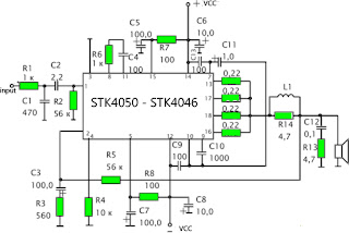

Schematics Amplifier STK4050-STK4046


PCB Layout Amplifier

Series Power Supply for Power Amplifier 200Watt By STK4050 been displayed in one image with a series of "Power Amplifier" 200Watt With STK4050 above. IC STK 4050 in this series there are several types on the market including STK4050II, STK4050V and STK4050.

And below is a list of STK ICs are used for a good quality amplifier.
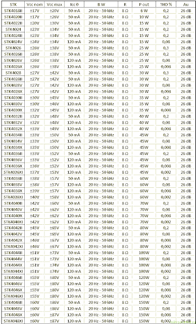
Datasheet STK IC Amplifier
ReadMore..

3 Transistor Audio Amplifier Circuit for 80 mW

This circuit is for amplifier 80 mW uses positive feedback to get a little more amplitude to the speaker. This is a simple design for a small amplifier. This has a disadvantage in that as the output moves positive, the drop across the 470 ohm resistor decreases which reduces the base current to the top NPN transistor. Thus the output cannot move all the way to the + supply because there wouldnt be any voltage across the 470 resistor and no base current to the NPN transistor. This is the figure of the circuit.


In this circuit, the 1K load resistor is tied to the speaker so that as the output moves negative, the voltage on the 1K resistor is reduced, which aids in turning off the top NPN transistor. When the output moves positive, the charge on the 470uF capacitor aids in turning on the top NPN transistor. The original circuit in the radio used a 300 ohm resistor where the 2 diodes are shown but I changed the resistor to 2 diodes so the amp would operate on lower voltages with less distortion. The transistors shown 2n3053 and 2n2905 are just parts I used for the other circuit above and could be smaller types. Most any small transistors can be used, but they should be capable of 100mA or more current. A 2N3904 or 2N3906 are probably a little small, but would work at low volume.

The 2 diodes generate a fairly constant bias voltage as the battery drains and reduces crossover distortion. But you should take care to insure the idle current is around 10 to 20 milliamps with no signal and the output transistors do not get hot under load. The circuit should work with a regular 8 ohm speaker, but the output power may be somewhat less. To optimize the operation, select a resistor where the 100K is shown to set the output voltage at 1/2 the supply voltage (4.5 volts). This resistor might be anything from 50K to 700K depending on the gain of the transistor used where the 3904 is shown.

ReadMore..

RF Fm 88 108 MHz 20W amplifier

This Fm rf power amplifier has 2 transistors from Philips : BLV 10 and BLW 87. The 2 rf transistors work in class C and this fm amplifier has a total gain of 21dB ( 100 X ) and efficiency 55 – 65%.
One low pass filter with 9 components ensures 60dB rejection on the second harmonic. There is no need for tune-up to cover the whole 88 – 108 MHz FM frequencies.


source [link] 
ReadMore..