Showing posts with label simple. Show all posts

Wednesday, December 25, 2013

Simple Infra red Receiver

This very simple infra-red receiver is intended to form an infra-red remote control system with the simple infra-red transmitter described in this site. The system does not use any kind of coding or decoding, but the carrier of the transmitter is modified in a simple manner to provide a constant switching signal. Since the receive module, IC1, switches from low to high (in the quiescent state, the output is high) when the carrier is received for more than 200 milliseconds, the carrier is transmitted in the form of short pulse trains. This results in a pulse at the output of the receiver that has a duty cycle which is just larger than 12.5%. The carrier frequency used in the system is 36 kHz, so that the output frequency of IC1 is 281.25 Hz.

Infra-red Receiver Circuit diagram :


This signal is rectified with a time constant that is long enough to ensure good smoothing, so that darlington T1 is open for as long as the received signal lasts. A drawback of this simple system is that it may pick up signals transmitted by another infra-red (RC5) controller. In this case, only the envelopes of the pulse trains would appear at the output of T1. This effect may, of course, be used intentionally. For instance, the receiver may be used to drive an SLB0587 dimmer. Practice has shown that the setting of the SLB0587 is not affected by the RC5 pulses. The receiver draws a current of about 0.5 mA.

Source : www.ecircuitslab.com/2011/05/infra-red-receiver-circuit.html
ReadMore..

Sunday, December 22, 2013

Simple Video Amplifier

The video amplifier in the diagram is a well-known design. Simple, yet very useful, were it not for the ease with which the transistors can be damaged if the potentiometers (black level and signal amplitude) are in their extreme position. Fortunately, this can be obviated by the addition of two resistors.

Circuit diagram :

Simple Video Amplifier-Circuit Diagram Simple Video Amplifier Circuit Diagram


If in the diagram R 3 and R 4 were direct connections, as in the original design, and P 1 were fully clockwise and P 2 fully anticlockwise, such a large base current would flow through T 1 that this transistor would give up the ghost. Moreover, with the wiper of P 2 at earth level, the base current of T 2 would be dangerously high. Resistors R 3 and R 4 are sufficient protection against such mishaps, since they limit the base currents to a level of not more than 5 mA.

Shunt capacitor C 4 prevents R 4 having an adverse effect on the amplification.

ReadMore..

Sunday, September 29, 2013

Simple Knock Alarm With Piezo Sensor

This circuit uses a thin piezoelectric sensor to sense the vibrations generated by knocking on a surface; eg, a door or table. Basically, it amplifies and processes the signal from the sensor and sounds an alarm for a preset period. In operation, the piezoelectric sensor converts mechanical vibration into an electrical signal. This sensor can be attached to a door, a cash box, cupboard, etc using adhesive. A 1-1.5m long shielded cable can then be connected between the sensor plate and the input of the circuit. The signal generated by the sensor is amplified by transistors Q1-Q3 which are wired as common-emitter amplifiers.

Simple knock alarm with piezo sensor circuit schematic

The signal is then rectified by diode D1 and amplified by transistors Q4-Q6. As shown, the output from Q6s collector is fed to pin 4 (reset) of 555 timer IC1. This is wired as an astable multivibrator. Each time Q6 turns on, its collector goes high and IC1 activates and produces an alarm tone in the speaker. The alarm automatically turns off 10s after knocking ceases - ie, the time taken for the 22µF capacitor on Q4s emitter to discharge. Finally, note that it may be necessary to adjust the 470O resistor in Q6s collector circuit to ensure that IC1 remains off in the absence of any perceptible knock. A value somewhere between 220O and 680O should be suitable.
ReadMore..

Saturday, August 10, 2013

Simple Light Dependent Resistors

LDRs or lightweight Dependent Resistors are terribly helpful particularly in light/dark sensor circuits. Normally the resistance of an LDR is incredibly high, typically as high as a thousand 000 ohms, however once they are illuminated with lightweight resistance drops dramatically.


 The animation opposite shows that when the torch is turned on, the resistance of the LDR falls, permitting current to have it.Circuit Wizard software has been used to show, the vary of values of a ORP12, LDR .
When a light-weight level of a thousand lux (bright light) is directed towards it, the resistance is 400R (ohms).


When a light-weight level of ten lux (very low light level) is directed towards it, the resistance has risen dramatically to ten.43M (10430000 ohms).

This is an example of a light-weight sensor circuit :

When the sunshine level is low the resistance of the LDR is high. This prevents current from flowing to the bottom of the transistors. Consequently the LED doesnt lightweight. However, when lightweight shines onto the LDR its resistance falls and current flows into the bottom of the primary transistor and then the second transistor. The LED lights.

The preset resistor will be turned up or right down to increase or decrease resistance, during this means it will build the circuit additional or less sensitive. Link

ReadMore..

Thursday, August 8, 2013

Simple Automatic Switch For Audio Power Amplifier

Circuit of an automatic switch for audio power amplifier stage is presented here. The circuit uses stereo preamplifier output to detect the presence of audio to switch the audio power amplifier on only when audio is present. The circuit thus helps curtail power wastage. IC1 is used as an inverting adder. The input signals from left and right channels are combined to form a common signal for IC2, which is used as an open loop comparator. IC3 (NE556) is a dual timer. Its second section, i.e., IC3(b), is configured as monostable multivibrator. Output of IC3(b) is used to switch the power amplifier on or off through a Darlington pair formed by transistors T1 and T2. IC3(a) is used to trigger the monostable multivibrator whenever an input signal is sensed.

Circuit diagram:
Automatic Switch For Audio Power Amplifier-Circuit-Diagram
Automatic Switch For Audio Power Amplifier Circuit Diagram

Under ‘no signal’ condition, pin 3 of IC2 is negative with respect to its pin 2. Hence the output of IC2 is low and as a result output of IC3(a) is high. Since there is no trigger at pin 8 of IC3(b), the output of IC3(b) will be low and the amplifier will be off. When an input singal is applied to IC1, IC2 converts the inverted sum of the input signals into a rectangular waveform by comparing it with a constant voltage which can be controlled by varying potentiometer VR1. When the output of IC2 is high, output pin 5 of IC3 goes low, thus triggering the monostable multivibrator. As soon as the audio input to IC1 stops, pin 5 of IC3 goes high and pin 1 of IC3 discharges through capacitor C3, thus resetting the monostable multivibrator. 

Hence, as long as input signals are applied, the amplifier remains ‘on.’ When the input signals are removed, i.e., when signal level is zero, the amplifier switches off after the mono flip-flop delay period determined by the values of resistor R8 and capacitor C3. If no input signals are sensed within this time, the amplifier turns off—else it remains on. Power supply for the circuit can be obtained from the power supply of the amplifier. Hence, the circuit can be permanently fitted in the amplifier box itself. The main switch of the amplifier should be always kept on. Resistors R1 and R2 are used to divide single voltage supply into two equal parts.

Capacitors C1 and C2 are used as regulators and also as an AC bypass for input signals. Diode D1 is used so that loading fluctuations in power amplifier do not affect circuit regulation. Transisitor T2 acts as a high voltage switch which may be replaced by any other high voltage switching transistor satisfying amplifier current requirements. Value of resistor R10 should be modified for large current requirement. The LED glows when the amplifier is on. The circuit is very useful and relieves one from putting the amplifier on and off every time one plays a cassette or radio etc.


http://streampowers.blogspot.com/2012/06/simple-automatic-switch-for-audio-power_11.html
ReadMore..

Tuesday, July 9, 2013

Simple 9 V Battery Replacement

This circuit was originally designed to power a motorcycle intercom from the vehicle supply system. This type of intercom, which is used for communication between driver and passenger, generally requires quite a bit of power. In order to improve intelligibility there is often elaborate filtering and a compander is sometimes used as well. The disadvantage is that a battery doesn’t last very long. You could use rechargeable batteries, of course, but that is often rather laborious. It seems much more obvious to use the motorcycle power supply instead. 

9-V Battery Replacement Circuit Diagram
Power-Supply-Circuit-Diagram

A 9-V converter for such an application has to meet a few special requirements. For one, it has to prevent interference from, for example, the ignition system reaching the attached circuit. It is also preferable that the entire circuit fits in the 9-V battery compartment. This circuit meets these requirements quite successfully and the design has nonetheless remained fairly simple. In the schematic we can recognise a filter, followed by a voltage regulator and a voltage indicator. D1, which protects the circuit against reverse polarity, is followed by an LC and an RC filter (C3/L1/L2/C1/R1/C2). This filter excludes various disturbances from the motorcycle power system. Moreover, the design with the 78L08 and D3 ensures that the voltage regulator is operating in the linear region. The nominal sys-tem voltage of 14 V can some-times sag to about 12 V when heavy loads such as the lights are switched on. 

Although the circuit is obviously suitable for all kinds of applications, we would like to mention that it has been extensively tested on a Yamaha TRX850. These tests show that the converter functions very well and that the interference suppression is excellent. Link
ReadMore..

Friday, July 5, 2013

Simple 600W Audio Amplifier Circuit Diagram

The 600W Audio Amplifier Circuit Diagram is based around {LM4702}manufactured by NATIONAL semiconductors&{MJ11029-MJ11028} by ON semiconductors It is a high fidelity audio power amplifier. Designed for demanding consumer and pro-audio applications. You can also use this circuit with AV receivers, Audiophile power amps, Pro Audio High voltage industrial applications etc Amplifier output power maybe scaled by changing the supply voltage and number of output devices. The circuit includes thermal shutdown circuitry that activates when the die temperature exceeds 150°c. CIRCUIT’s mute function, when activated, mutes the input drive signal and forces the amplifier output to a quiescent state.

 Simple 600W Audio Amplifier Circuit Diagram

Simple 600W Audio Amplifier Circuit Diagram

Power:
Maximum Output power @ 8ohms : 300watt
Absolute max power supply voltage :±38V to ±40V
Recommended power supply voltage :±30V to ±35V
ReadMore..

Wednesday, July 3, 2013

Simple Solar Flasher

This Simple Solar Flasher circuit is a single transistor fly back (Joule Thief) circuit that features a third coil. With it, flash duration and brightness is much enhanced, without resorting to large value capacitors.

Circuit Diagram:


ReadMore..

Friday, April 12, 2013

How to Make a Simple Timer Circuit Using IC 555


A timer is a device which produces a delay period after which an external connected electrical load is triggered. The produced time delay is normally adjustable and the user has the freedom to set the time period as desired. There are many ways of making simple timer circuits using different ICs and discrete components; here we discuss one such circuit using the ubiquitous IC 555.


The IC 555 is a pretty common electronic part among the electronic enthusiasts and is also very popular due to the involved simple configurations and low component count.

The two popular multivibrator modes of operation that’s associated with this IC are the astable mode, and the monostable mode. Both of these are useful configurations and have plenty of different applications.

For the present design we incorporate the second mode of operation, which is the monostable mode.

In this mode of operation the IC is configured to receive a trigger externally, so that it’s output changes state, meaning if with reference to the ground if the output of the IC is zero, then it would become positive as soon as the trigger (momentary) is received at its input terminal.

This change in its output is sustained for a certain period if time, depending upon the external time determining components. Normally the time determining components are in the form of a resistor and a capacitor which together determine or fix the time period for which the IC output would hold its “high” position.

By changing either the value of the capacitor or the resistor, the timing can be altered as desired. The above time fixing components are termed as the RC component.

The figure shows a very straightforward design where the IC 555 forms the central controlling part of the circuit. As discussed in the above section, the IC is in its standard monostable mode.

Pin #2 receives the external timing trigger from a push-to-ON switch. Once this switch is pushed, the circuit pulls its output to a positive potential   and holds it until the predetermined time delay lapses.

The entire circuit can be built over a small piece of general PCB and housed inside a neat looking plastic enclosure along with the battery.

The output may be ideally connected to a buzzer for receiving the warning alarm after the set time lapses.

Parts List

R1, R4 = 4K7,
R2 = 10K,
R3 = 1M pot,
C1 = 0.47uF,
C2 = 1000uF/25V,
C3 = 0.01uF,
IC1 = 555,
Bz1 = Piezo Buzzer,
Push Button = push to ON switch

A circuit design requested by Mr.Bourgeoisie:


ReadMore..

Thursday, April 11, 2013

Simple Infra red Receiver

This very simple infra-red receiver is intended to form an infra-red remote control system with the simple infra-red transmitter described in this site. The system does not use any kind of coding or decoding, but the carrier of the transmitter is modified in a simple manner to provide a constant switching signal. Since the receive module, IC1, switches from low to high (in the quiescent state, the output is high) when the carrier is received for more than 200 milliseconds, the carrier is transmitted in the form of short pulse trains. This results in a pulse at the output of the receiver that has a duty cycle which is just larger than 12.5%. The carrier frequency used in the system is 36 kHz, so that the output frequency of IC1 is 281.25 Hz.

Infra-red Receiver Circuit diagram :


This signal is rectified with a time constant that is long enough to ensure good smoothing, so that darlington T1 is open for as long as the received signal lasts. A drawback of this simple system is that it may pick up signals transmitted by another infra-red (RC5) controller. In this case, only the envelopes of the pulse trains would appear at the output of T1. This effect may, of course, be used intentionally. For instance, the receiver may be used to drive an SLB0587 dimmer. Practice has shown that the setting of the SLB0587 is not affected by the RC5 pulses. The receiver draws a current of about 0.5 mA.

Source : www.ecircuitslab.com/2011/05/infra-red-receiver-circuit.html
ReadMore..

Wednesday, April 10, 2013

Simple 16 Stage Bi Directional LED Sequencer

The bi-directional sequencer uses a 4 bit binary up/down counter (CD4516) and two "1 of 8 line decoders" (74HC138 or 74HCT138) to generate the popular "Night Rider" display. A Schmitt Trigger oscillator provides the clock signal for the counter and the rate can be adjusted with the 500K pot. Two additional Schmitt Trigger inverters are used as a SET/RESET latch to control the counting direction (up or down). Be sure to use the 74HC14 and not the 74HCT14, the 74HCT14 may not work due to the low TTL input trigger level. When the highest count is reached (1111) the low output at pin 7 sets the latch so that the UP/DOWN input to the counter goes low and causes the counter to begin decrementing. 

When the lowest count is reached (0000) the latch is reset (high) so that the counter will begin incrementing on the next rising clock edge. The three lowest counter bits (Q0, Q1, Q2) are connected to both decoders in parallel and the highest bit Q3 is used to select the appropriate decoder. The circuit can be used to drive 12 volt/25 watt lamps with the addition of two transistors per lamp as shown below in the section below titled "Interfacing 5 volt CMOS to 12 volt loads"

ReadMore..

Friday, April 5, 2013

How to Make a Simple VU Meter Circuit at Home

VU meter or a volume unit meter is a device used for indicating the music volume output from an amplifier or a loudspeaker system. It may be also considered as a device for displaying the PMPO of the amplifier at a particular volume setting.
Though the unit looks quite  technical, which is applied as a measuring device of audio power, in real terms these are more like decorative ornaments of an amplifier. Without such devices attached, an amplifier system would look quite dull and without any juice.
The varying response from a VU meter certainly gives a whole new dimension to a sound system making it more dynamic with its features.
Prior to the days when LEDs were not so popular, moving coil meter type of displays were commonly incorporated as VU meters and surely these units with there back lights ON produced a distinctive visual effect as their needles deflected from left to right displaying the varying pitch of the connected audio system.
With the advent of  the LEDs, the moving coil displays slowly got replaced with the ones which incorporated LEDs.
With color effect at its disposal, LEDs became the HOT favorites as far as VU meter were concerned, even today amplifiers employ a LED VU graph for displaying the music power in an amplifier.
For electronic hobbyists who are rather more interested in building a particular required gagdet right at home instead of buying a commercial piece, this cool VU meter circuit will interest them if they are intending to make one for their music system.
The circuit of a simple LED VU meter explained here uses the outstanding chip LM3915 from TEXAS Instruments.
The circuit diagram shows a very simple configuration employing two of the above ICs in the cascaded form for producing a good 20 LED sequencing bar type indication.
The music input is applied across pin #5 and ground of the IC. The music input can be directly derived from the speaker terminals of the music system.
R3 has been stationed for adjusting the typical dB levels between the LEDs for enabling visually more enhanced sequencing pattern in response to the fed music input.
The diagram shows a separate power supply being used for the circuit, however if the amplifier supports a 12 volt stabilized power supply, can be used for powering the circuit as well, this would help to get rid of the extra bulk involving the transformer and the associated rectification circuitry.
The color of the LEDs may be selected as indicated in the diagram or may be altered as desired by the user.
Everything is pretty straight forward and can be simply built over a general purpose board.
Assemble the IC first and then go on fixing the rest of the components and connect then to the relevant pin outs of the IC.
The LEDs should be soldered at the end, such that all of them are arranged in a straight line, preferably at the edge of the PCB.
An external enclosure may be used for housing the assembled circuit or possibly the circuit may be installed in the amplifier dashboard itself, if situation permits the required drilling and fittings.


ReadMore..

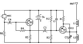
Simple FM transmitter with 2N3904

simple FM transmitter
In this section discuss about the series of mini fm transmitter, with broadcast coverage of about 300-400 meters. when using a 9 volt working voltage, the transmit power of about 300 meters and when using the working voltage 12 volts, the range of about 400-450 meters, depending on the antenna you use.

This scheme of simple fm transmitter
simple FM transmitter

For L1 and L2 windings 5 times the wrap, you can use a pen to fill melilitnya so neat and after lepaslah content of these pens. C5 is used for placement of broadcasting frequencies, can be tuned between 88-108 mhz, to reach further use steering antenna or Yagi antenna.

Part List
C1 = 0.001uF
C2 = 5.6pF
C3 = 10uF
C4 = 10uF
C5 = 3 - 18pF Adjustable capacitor
R1 = 270R
R2 = 4.7K
R3 = 10K
R4 = 100K
R5 = 4.7K
R6 = 4.7K
Q1 = 2N2222A
Q2 = 2N3904
L1 = 5 turn
L2 = 5 turn
ReadMore..