Wednesday, August 14, 2013
Christmas star with 40 LEDs
This is an ordinary LED circuit.Here you must be creative when you build this circuit.Really If you are creative you can make really really fantastic Christmas star.On the other hand you can use this for your Christmas tree even.

Note
# Use 6v for this circuit
# Use blue colour LEDs to get the maximum attraction.
ReadMore..
Note
# Use 6v for this circuit
# Use blue colour LEDs to get the maximum attraction.

Tuesday, August 13, 2013
Thermostat Wiring Conventional Furnace Conditioner Split
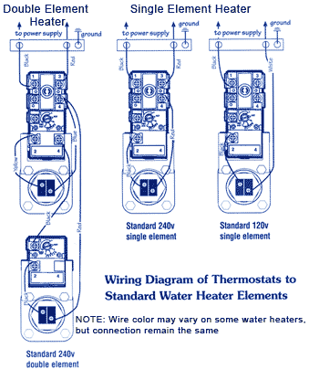
Water Heater Typical Electric Water Heater Construction Wiring Diagram.

Wiring And Connectors Locations Of Honda Accord Air Conditioning.

Diagram Complete With Its Related Parts And Components Assembly.

Schematic Diagram For Electronic Thermostat Of Isuzu Trooper Air.

Thermostat Wiring For Conventional Gas Furnace Air Conditioner Split.

Sanyo Air Conditioners And Heat Pump Electrical Wiring Diagram.

About 1997 Chevrolet Venture Charging Circuit And Wiring Diagram.

The Following Electrical Wiring Diagram Manual Apply For 1996 Mazda.

Digital Thermostat Hunter Wiring Diagram 1 Jpg.

Wiring Diagram Of Nuheat Solo Programmable Thermostat Around.
Monday, August 12, 2013
Drinking Water Alarm
Drinking Water Alarm
State Jal Boards supply water for limited duration in a day. Time of
water supply is decided by the management and the public does not know
the same. In such a situation, this water alarm circuit will save the
people from long wait as it will inform them as soon as the water supply
starts. At the heart of this circuit is a small water sensor. For
fabricating this water sensor, you need two foils—an aluminium foil and a
plastic foil. You can assemble the sensor by rolling aluminium and
plastic foils in the shape of a concentric cylinder. Connect one end of
the insulated flexible wire on the aluminium foil and the other end to
resistor R2. Now mount this sensor inside the water tap such that water
can flow through it uninterrupted. To complete the circuit, connect
another wire from the junction of pins 2 and 6 of IC1 to the water
pipeline or the water tap itself. The working of the circuit is simple.
 Timer
Timer
555 is wired as an astable multivibrator. The multivibrator will work
only when water flows through the water tap and completes the circuit
connection. It oscillates at about 1 kHz. The output of the timer at pin
3 is connected to loudspeaker LS1 via capacitor C3. As soon as water
starts flowing through the tap, the speaker starts sounding, which
indicates resumption of water supply. It remains ‘on’ until you switch
off the circuit with switch S1 or remove the sensor from the tap. The
circuit works off a 9V battery supply. Assemble the circuit on any
general-purpose PCB and house in a suitable cabinet. The water sensor is
inserted into the water tap. Connect the lead coming out from the
junction of 555 pins 2 and 6 to the body of the water tap. Use on/off
switch S1 to power the circuit with the 9V PP3 battery.
Sunday, August 11, 2013
Very Low Power 32kHz Oscillator
The 32-kHz low-power clock oscillator offers numerous advantages over conventional oscillator circuits based on a CMOS inverter. Such inverter circuits present problems, for example, supply currents fluctuate widely over a 3V to 6V supply range, while current consumption below 250 µA is difficult to attain. Also, operation can be unreliable with wide variations in the supply voltage and the inverter’s input characteristics are subject to wide tolerances and differences among manufacturers. The circuit shown here solves the above problems. Drawing just 13 µA from a 3V supply, it consists of a one-transistor amplifier/oscillator (T1) and a low-power comparator/reference device (IC1).
 Very Low Power 32kHz Oscillator Circuit Diagram
The base of T1 is biased at 1.25 V using R5/R4 and the reference in IC1. T1 may be any small-signal transistor with a decent beta of 100 or so at 5 µA (defined here by R3, fixing the collector voltage at about 1 V below Vcc). The amplifier’s nominal gain is approximately 2 V/V. The quartz crystal combined with load capacitors C1 and C3 forms a feedback path around T1, whose 180 degrees of phase shift causes the oscillation. The bias voltage of 1.25 V for the comparator inside the MAX931 is defined by the reference via R2. The comparator’s input swing is thus accurately centred around the reference voltage.
Operating at 3 V and 32 kHz, IC1 draws just 7 µA. The comparator output can source and sink 40 mA and 5 mA respectively, which is ample for most low-power loads. However, the moderate rise/fall times of 500 ns and 100 ns respectively can cause standard, high-speed CMOS logic to draw higher than usual switching currents. The optional 74HC14 Schmitt trigger shown at the circuit output can handle the comparator’s rise/fall times with only a small penalty in supply current.
Source by : Streampowers
Saturday, August 10, 2013
Simple Light Dependent Resistors
LDRs or lightweight Dependent Resistors are terribly helpful particularly in light/dark sensor circuits. Normally the resistance of an LDR is incredibly high, typically as high as a thousand 000 ohms, however once they are illuminated with lightweight resistance drops dramatically.

The animation opposite shows that when the torch is turned on, the resistance of the LDR falls, permitting current to have it.Circuit Wizard software has been used to show, the vary of values of a ORP12, LDR .
When a light-weight level of a thousand lux (bright light) is directed towards it, the resistance is 400R (ohms).

When a light-weight level of ten lux (very low light level) is directed towards it, the resistance has risen dramatically to ten.43M (10430000 ohms).
This is an example of a light-weight sensor circuit :
When the sunshine level is low the resistance of the LDR is high. This prevents current from flowing to the bottom of the transistors. Consequently the LED doesnt lightweight. However, when lightweight shines onto the LDR its resistance falls and current flows into the bottom of the primary transistor and then the second transistor. The LED lights.
The preset resistor will be turned up or right down to increase or decrease resistance, during this means it will build the circuit additional or less sensitive. Link
When the sunshine level is low the resistance of the LDR is high. This prevents current from flowing to the bottom of the transistors. Consequently the LED doesnt lightweight. However, when lightweight shines onto the LDR its resistance falls and current flows into the bottom of the primary transistor and then the second transistor. The LED lights.
The preset resistor will be turned up or right down to increase or decrease resistance, during this means it will build the circuit additional or less sensitive. Link

Friday, August 9, 2013
Battery Powered Night Lamp
This circuit is usable as a Night Lamp when a wall mains socket is not available to plug-in an ever running small neon lamp device. In order to ensure minimum battery consumption, one 1.5V cell is used and simple voltage doublers drives a pulsating ultra-bright LED: current drawing is less than 500µA. An optional Photo resistor will switch-off the circuit in daylight or when room lamps illuminate, allowing further current economy. This device will run for about 3 months continuously on an ordinary AA sized cell or for around 6 months on an alkaline type cell but, adding the Photo resistor circuitry, running time will be doubled or, very likely, triplicates. IC1 generates a square wave at about 4 Hz frequencies. C2 & D2 form voltage doublers, necessary to raise the battery voltage to a peak value able to drive the LED.

Parts:
R1 = 1M
R2 = 1M
R3 = 47K
R4 = LDR
C1 = 100nF-63V
C2 = 220uF-25V
D1 = Ultra Bright 10mm LED
D2 = 1N5819 B1 = 1.5V Battery or AA Cell
IC1 = 7555 CMos Timer IC
Notes:
* IC1 must be a CMos type: only these devices can safely operate at 1.5V supply or less. * If you do not need Photo resistor operation, omit R3 & R4 and connect pin 4 of IC1 to positive supply. * Ordinary LEDs can be used, but light intensity will be poor. * An ordinary 1N4148 type diode can be used instead of the 1N5819 Schottky-barrier type diode, but LED intensity will be reduced due to the higher voltage drop. * Any Schottky-barrier type diode can be used in place of the 1N5819, e.g. the BAT46, rated @ 100V 150mA.
ReadMore..
Parts:
R1 = 1M
R2 = 1M
R3 = 47K
R4 = LDR
C1 = 100nF-63V
C2 = 220uF-25V
D1 = Ultra Bright 10mm LED
D2 = 1N5819 B1 = 1.5V Battery or AA Cell
IC1 = 7555 CMos Timer IC
Notes:
* IC1 must be a CMos type: only these devices can safely operate at 1.5V supply or less. * If you do not need Photo resistor operation, omit R3 & R4 and connect pin 4 of IC1 to positive supply. * Ordinary LEDs can be used, but light intensity will be poor. * An ordinary 1N4148 type diode can be used instead of the 1N5819 Schottky-barrier type diode, but LED intensity will be reduced due to the higher voltage drop. * Any Schottky-barrier type diode can be used in place of the 1N5819, e.g. the BAT46, rated @ 100V 150mA.
Thursday, August 8, 2013
Simple Automatic Switch For Audio Power Amplifier
Circuit of an automatic switch for audio power amplifier stage is presented here. The circuit uses stereo preamplifier output to detect the presence of audio to switch the audio power amplifier on only when audio is present. The circuit thus helps curtail power wastage. IC1 is used as an inverting adder. The input signals from left and right channels are combined to form a common signal for IC2, which is used as an open loop comparator. IC3 (NE556) is a dual timer. Its second section, i.e., IC3(b), is configured as monostable multivibrator. Output of IC3(b) is used to switch the power amplifier on or off through a Darlington pair formed by transistors T1 and T2. IC3(a) is used to trigger the monostable multivibrator whenever an input signal is sensed.
Circuit diagram:

Automatic Switch For Audio Power Amplifier Circuit Diagram
Under ‘no signal’ condition, pin 3 of IC2 is negative with respect to its pin 2. Hence the output of IC2 is low and as a result output of IC3(a) is high. Since there is no trigger at pin 8 of IC3(b), the output of IC3(b) will be low and the amplifier will be off. When an input singal is applied to IC1, IC2 converts the inverted sum of the input signals into a rectangular waveform by comparing it with a constant voltage which can be controlled by varying potentiometer VR1. When the output of IC2 is high, output pin 5 of IC3 goes low, thus triggering the monostable multivibrator. As soon as the audio input to IC1 stops, pin 5 of IC3 goes high and pin 1 of IC3 discharges through capacitor C3, thus resetting the monostable multivibrator.
Hence, as long as input signals are applied, the amplifier remains ‘on.’ When the input signals are removed, i.e., when signal level is zero, the amplifier switches off after the mono flip-flop delay period determined by the values of resistor R8 and capacitor C3. If no input signals are sensed within this time, the amplifier turns off—else it remains on. Power supply for the circuit can be obtained from the power supply of the amplifier. Hence, the circuit can be permanently fitted in the amplifier box itself. The main switch of the amplifier should be always kept on. Resistors R1 and R2 are used to divide single voltage supply into two equal parts.
Capacitors C1 and C2 are used as regulators and also as an AC bypass for input signals. Diode D1 is used so that loading fluctuations in power amplifier do not affect circuit regulation. Transisitor T2 acts as a high voltage switch which may be replaced by any other high voltage switching transistor satisfying amplifier current requirements. Value of resistor R10 should be modified for large current requirement. The LED glows when the amplifier is on. The circuit is very useful and relieves one from putting the amplifier on and off every time one plays a cassette or radio etc.
http://streampowers.blogspot.com/2012/06/simple-automatic-switch-for-audio-power_11.html
Subscribe to:
Posts (Atom)